What is EPIC?
EPIC (Earth Polychromatic Imaging Camera) is a 10-channel spectroradiometer (317 – 780 nm) onboard NOAA’s DSCOVR (Deep Space Climate Observatory) spacecraft. EPIC provides 10 narrow band spectral images of the entire sunlit face of Earth using a 2048x2048 pixel CCD (Charge Coupled Device) detector coupled to a 30-cm aperture Cassegrain telescope (Figure 1).
The DSCOVR spacecraft is located at the Earth-Sun Lagrange-1 (L-1) point giving EPIC a unique angular perspective that will be used in science applications to measure ozone, aerosols, cloud reflectivity, cloud height, vegetation properties, and UV radiation estimates at Earth's surface.
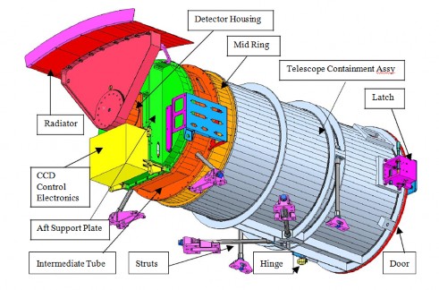
Figure 1. EPIC 30 cm f/9.6 Cassegrain telescope showing the area containing the CCD (red) filter wheel (green).
Ten Channels
The ten channels are listed in Table 1 along with their primary applications for the data that will be obtained for the entire globe (sunrise to sunset) every 60 to 100 minutes.
Field of view that EPIC sees
The EPIC instrument has a field of view (FOV) of 0.62 degrees, which is sufficient to image the entire Earth, which has a nominal size of 0.5 degrees. Because of the tilted (Lissajous) orbit about the L‐1 point, the apparent angular size of the Earth changes during the 6-month orbital period from 0.45 to 0.53 degrees.
Table 1.
EPIC Wavelengths and main data products

Figure 2. A perfect launch of the DSCOVR spacecraft from Cape Canaveral, Florida on February 11, 2015 leading to a minimum use of onboard fuel to achieve final orbit around Lagrange-1.
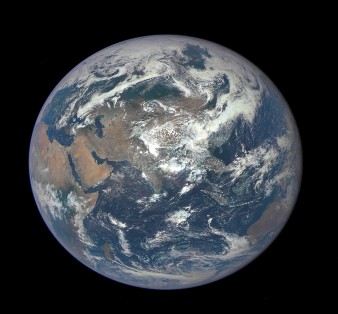
Figure 3. EPIC image of the Earth from Lagrange-‐1 taken on July 6, 2015.
Image Sizes
The first image released to the public (Figure 3) shows Africa, Middle East, India and China, it also shows the size of the Earth relative to EPIC’s field of view (black area). The pixel size projected onto the Earth near the equator is 8x8 km squared with an optical resolution of about 12x12 km squared for visible wavelengths. The projected pixel size of images increases with distance from the equator, doubling by latitude of 60 degrees. To reduce the amount of data transmitted from DSCOVR, four pixels are averaged onboard the spacecraft yielding downloaded images of 1024 x1024 elements at an estimated optical resolution of approximately 24x24 km squared.
A technical schematic of EPIC
A technical schematic of the telescope (Figure 4) shows the primary and secondary mirrors, focusing or Field Lens Group (FLG), and the filter wheel location just in front of the CCD. In addition to focusing the image on the CCD, the FLG reduces the aberrations inherent in a Cassegrain design. In the EPIC system, the FLG is physically located between the primary mirror and the filter wheels. Along with new narrow-band wavelength filters with improved antireflection coatings, the original FLG was replaced with an improved design to reduce stray light. The optical efficiency of the telescope permits between 70 to 80% of the photons entering the telescope to reach the CCD detector.
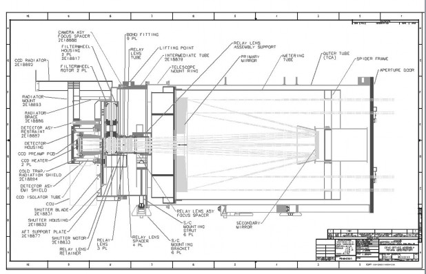
Figure 4. Schematic of the EPIC telescope.
DSCOVR Earth science instruments
The DSCOVR spacecraft with the DSCOVR Earth Science instruments NISTAR and EPIC are shown in Figure 5 relative to the size of persons working with them. The National Institute of Standards and Technology (NIST) Advanced Radiometer (NISTAR) is on the left side at the top of the spacecraft. It measures the absolute "irradiance" as a single pixel integrated over the entire sunlit face of the Earth. On the right side at the top of the spacecraft, EPIC is shown with the circular door closed. The door was opened when the spacecraft achieved orbit at L-1 in June 2015.
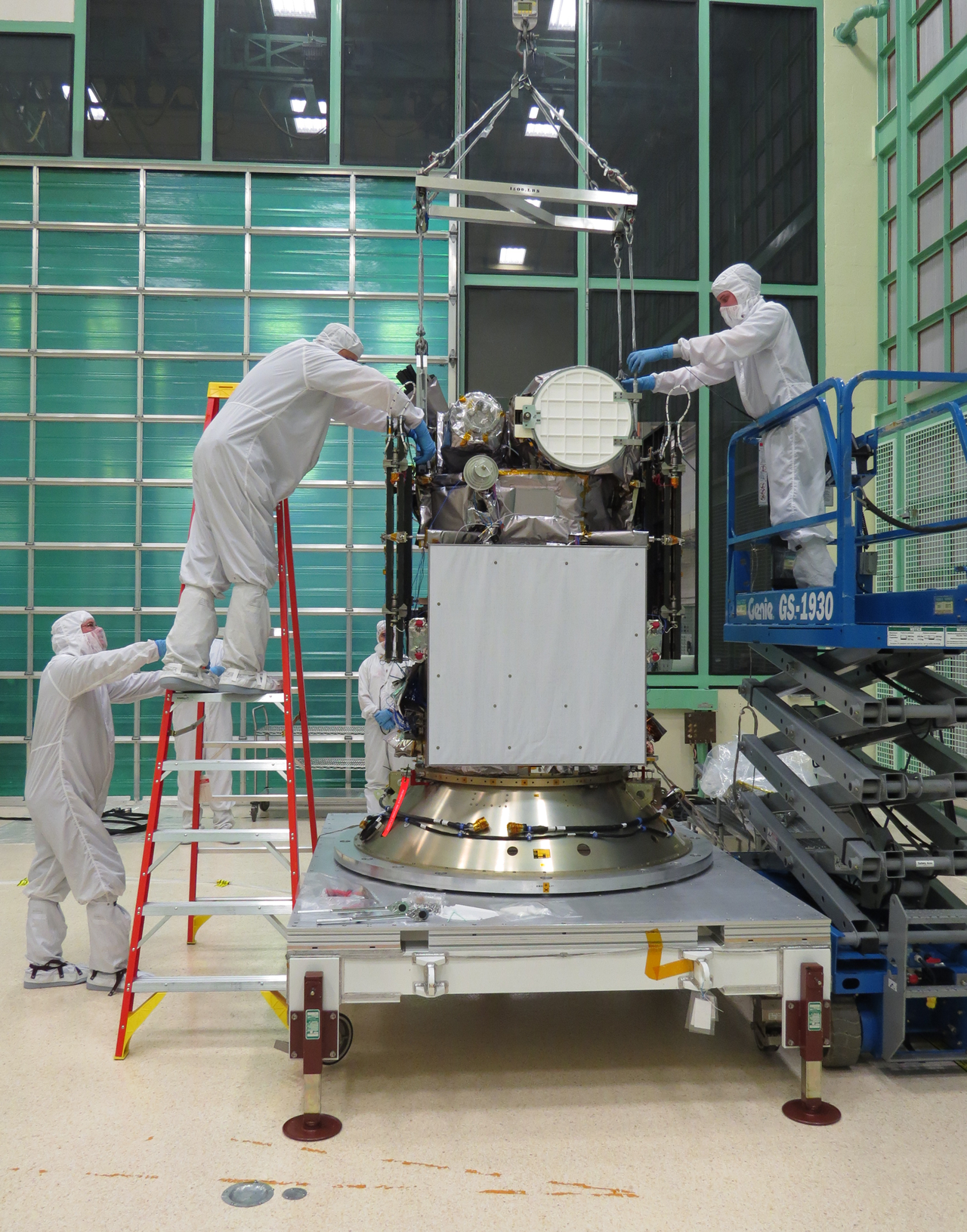
Figure 5. Assembling the DSCOVR Earth Science Instruments on the spacecraft.
Double Filter Wheel
Inside the EPIC telescope is a double filter wheel with 12 spaces for 10 filters plus 2 open holes (Figure 6) arranged with six holes in each wheel. The filters are positioned by computer controlled stepper motors in a pre-¬‐determined sequence that can be altered by ground commands.
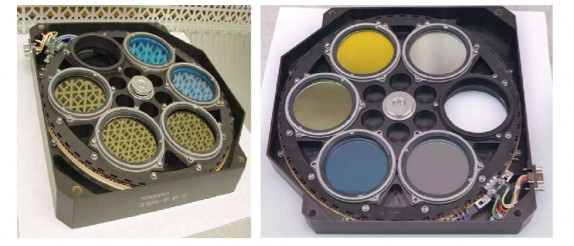
Figure 6. The EPIC double filter wheel
Rotating shutter and exposure times
In front of the filterwheels there is a rotating shutter wheel mechanism (Figure 7) showing 3 slots. The narrow slot is intended for exposures less than 10 milliseconds, the medium slot is used for exposures of 10 to 46 milliseconds, and the wide slot is used for exposures > 46 ms. For 10 to 46 ms exposures, the shutter blade is moved so that the middle sized slot crosses the light path in a single motion. For exposures longer than 46 ms, the wide slot is used. To obtain the various exposures, the blade slows down, then speeds up to complete the exposure. For an exposure longer than about 60 ms, the blade comes to a complete stop in the open position prior to closing. . In the refurbished design, the filter widths were adjusted so that the narrowest slot is not used so as to improve the uniformity of exposure across the CCD.
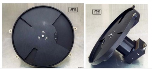
Figure 7. Shutter wheel assembly showing 3 shutter positions, 1) Narrow, 2) Medium, and 3) wide.
CCD Characteristics
The focal plane contains a 2048x2048 pixel backside thinned CCD that is hafnium coated to optimize sensitivity (quantum efficiency) down to 300 nanometers. The CCD is passively cooled to approximately ‐20°C (-4°F) to reduce the zero-light noise (dark current) and other noise effects. In normal operation, the CCD will be read out from one of the opposite corners at 500 kHz. Since the entire array can be read out from either side, it provides some measure of redundancy. The CCD characteristics are summarized in Table 2. The CCD quantum efficiency shown in Figure 8 illustrates a reasonable response at both ends of the desired spectrum, 317 nanometers (80%) and 780 nanometers (50%).
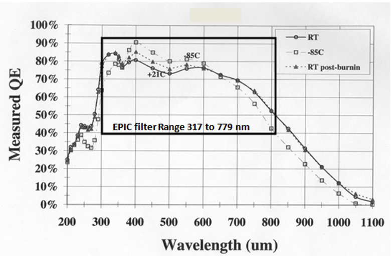
Figure 8. CCD quantum efficiency showing the useful range of the EPIC instrument (box).
Table 2. CCD Characteristics
EPIC Mirrors and Telescope Components
The composition of the mirrors and structures are specifically made to minimize thermal expansion. Specifically, the mirrors are built from Zerodur with an aluminum coating overcoated with silicon dioxide SiO2 coating on the primary mirror and aluminum overcoated with Magnesium Flouride MgF2 on the secondary mirror. The structure maintaining the optical separation between the primary and secondary mirrors (metering tube) is a graphite composite cylinder designed to exhibit near-zero CTE (Coefficient of Thermal Expansion). The mechanical structure supporting the primary and secondary mirrors (between the mirrors and the metering tube) is Invar 36, also selected to minimize thermal expansion properties.
EPIC Filters
The EPIC filters were refurbished to have improved antireflection coatings and better out of band rejection (light from other wavelengths). Out of band leakage is very small (0.04 percent for 325 nanometers). The mean filter transmission functions are shown in Figure 9. For most science products, the measurements from each filter are combined in pairs as a ratio or difference. An exception is for estimating cloud reflectivity using 340 or 388 nanometers, where a single channel is used.
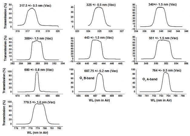
Figure 9. Mean filter transmission functions in percent
Corrections applied to images
A series of corrections must be applied before either realistic color images or science data products can be obtained. The major corrections are for “flat‐fielding” and stray light. “Flat-fielding” is based on measurements with a uniform light source to measure the differences in sensitivity for each of the 4 million pixels. The resulting correction map is applied to the measured counts from the CCD. Stray light was measured in the laboratory using a series of small diameter light sources entering the telescope and imaged on the CCD. A similar set of measurements has been performed on orbit using the moon. The illumination of pixels outside the main diameter of the light source was measured to produce a detailed matrix map of the entire stray light function (the effect of light directed at each pixel affecting every other pixel). The stray light correction is applied to every image. Other corrections are also applied based on laboratory measurements. For wavelengths longer than 550 nm there are back to front interference effects in the partially transparent CCD (etaloning) that must also be removed from the measured radiances.
User guide and a description for EPIC is available at https://avdc.gsfc.nasa.gov/pub/DSCOVR/DSCOVR-EPIC-Description.pdf